As I work to find an audience for Dwindle - the hardest problem I've ever worked on, by the way - I'm experimenting with different layouts. Specifically, I want games run on PC (including the browser) to look more like one would expect.
This means that I need to support both landscape and portrait layouts.
Tool Trouble
I've found an asset to help with this but it doesn't work perfectly. Especially: sometimes its behavior is a little surprising to developers and it was not set up very well for Unity's nested prefab feature. I use nested prefabs very heavily.
The result is that the tool works but, if I'm not very careful (which is most of the time), it can destabilize quickly.
I need tests that let me know what I've done something that triggers the layout asset I'm using and causes it to go berserk.
What to Test?
I have two lines of defense here: switching from invoking buttons programmatically to simulating clicks and directly testing the layout.
The former ensures that the buttons I'm invoking are actually clickable in the viewable area of the game - an assumption I could make up until recently.
The latter is a gigantic pain in the ass but was ultimately worth the effort.
I'm going to start laying out some of what I did on that front, here.
Defining a Meaningful Layout Requirement
It starts with a good specification and that means I need to know what a good specification for layout actually
is.
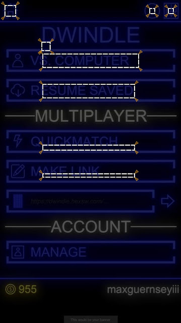
Not being a UI/UX expert, I settled on an SVG graphic that can be used to codify the specification and can be inspected visually.
I first had to decide what my requirements for the requirements were. The game is playable on a variety of Android devices as well as in a web browser. Additionally, it can be configured differently within those different form factors (for instance, there are no embedded ads when played on Kongregate).
So the tests I write need to either be (a) very flexible around changes in device form-factor/configuration for a channel or (b) finely tuned to a specific execution environment.
Neither of those is particularly appetizing options - UI testing never is. However, given the choice between too much flexibility or too much coupling, I'll take the former.
Right now, I define layouts in terms of two kinds of constraints. Not every constraint is defined for every requirement I specify. The two kinds of constraints are:
- Inner boxes - boxes that must be contained by the UI structure being examined.
- Outer boxes - boxes that must contain the UI structure being examined.
Note that this still gives me the ability to have a rigid definition if I want: just make the inner and outer boxes the same box.
Remember, I'm not trying to set up a test-driven layout, here. For a small project with one developer who is also the product owner and product manager, that would probably be overkill.
What I'm trying to set up is a system of alarms that lets me know when my layout asset has gone haywire and borked my game. That's a much less demanding task and the above constraints suit it nicely.
Codifying Layout Requirements
To represent these constraints, I chose to define a narrow convention within the SVG format:
- Anything can be in the document.
- Only rect, polygon, and polyline elements are actually parsed and used as specification directives. Everything else is disregarded.
- Dot-delimited id attributes represent a logical path within a specification file to any given constraint.
- The final step in a constraint's path represents the kind of rule applied to the shape in question.
- Additionally: For polylines and polygons, the first three coordinates of the path are treated as points on a parallelogram that defines the corresponding constraint. (I never use anything other than a rectangle but that's a kind of parallelogram, right).
For instance:
- A rect element with an id of "cheese.tacos.halfoff.inner" represents a box that must be inside whatever UI element is being tested.
- A circle element with an id of "important.control.outer" will be ignored because it is a circle.
- A polyline element with an id of "handle.bars.notsupported" will not be treated as a rule because the system cannot map "notsupported" to a constraint.
This gives me a fair amount of freedom to create a specification that, visually, tells a person what are the rules for a particular shape while allowing a test to use the exact same data to make the exact same determination.
Blogger makes it pretty hard to host SVGs - as do most companies, it seems. However, below is an embedded Gist for a specification. You can grab the code and look at it, yourself if you like.
Also, here's a rendering of the image, in case you don't want to go to the trouble of grabbing the code, saving it, and opening it up in a separate browser window:
 |
| A jpg-ified version of the SVG |
If you look at the gist, you can see what I did to make the little wedges without having to handcraft each one.
This leaves much to be desired but it also allows me to solve a lot of my problems.
Parsing it and computing the expected positions for an actual screen's size is pretty straightforward arithmetic. This entry is long, so I'll save that for another time so I can focus on a more interesting problem.
Defining a Test
Of course, this is just raw data. It's not a test. I need to add some context for it to be a truly useful specification. Here's a pared-down feature file.
Feature: Layout - Portrait
Background:
Given device orientation is portrait
Scenario: Position of application frame artifacts
Given main menu is active
# SNIPPED: Out of scope specifications
Then shapes conform to specifications (in file "Frame Specification - Buttons - Portrait.svg"):
| Layout Artifact | Rule |
| application return to main menu | home |
| main menu new single player game | start single player |
| main menu new multiplayer game | start multiplayer |
| main menu resume game | start resume |
What I've described, so far, allows me to set up the expected side of the tests. How do I bind it? How do I get my actuals?
It turns out the quest to do this gave me the tools to solve other problems (like using real taps instead of simulated ones).
Like everything that isn't painting a pretty picture for a first-person shooter, Unity doesn't make it easy to do this. It's not that any of the steps are difficult to do or understand. It's difficult to find what the steps are and string them together.
I take that to mean I'm doing something for which they have not planned, which is probably because not very many people are trying to do it.
For one thing, there are
two complementary ways of determining an object's on-screen shape. One way works for UI elements. The other works for game objects that are not rendered as part of what Unity calls a UI. That's another problem, I'll set aside for the moment, though. Let's just stick with UI.
I already have a way of getting information about the game out of the game. That's probable
another blog entry for later. Anyway, it allows me to instrument the game with testable properties and then query for those properties from my test.
Getting the Shape of Onscreen Objects
First, I need something to pass back and forth:
[DataContract]
public struct ObjectPositionData
{
  [DataMember]
  public Rectangle TransformShape;
  [DataMember]
  public Rectangle WorldShape;
  [DataMember]
  public Rectangle LocalShape;
  [DataMember]
  public Rectangle ScreenShape;
  [DataMember]
  public Rectangle ViewportShape;
}

[DataContract]
public struct Rectangle
{
  [DataMember]
  public Vector Origin;

  [DataMember]
  public Vector Right;

  [DataMember]
  public Vector Up;
  /* SNIPPED: Mathematical functions */
}

[DataContract]
public struct Vector
{
  [DataMember]
  public float X;
  [DataMember]
  public float Y;
  [DataMember]
  public float Z;
  /* SNIPPED: Mathematical functions */
}
Then I needed a way of populating it. For UI elements. That is about turning a RectTransform into its onscreen coordinates. Most importantly, I need the "viewport" coordinates, which mapped to the square (0,0)-(1,1). I could also use the screen coordinates, but both the screen coordinates and the viewport coordinates need a little massaging to be useful for the test infrastructure and the transformation for the viewport coordinates is trivial: y
new = 1 - y
original.
Extracting these coordinates is, of course, an obnoxious process. Everything has to be done through the camera and everything has to be treated like it's 3D - even when it's not. So, it starts by finding the "world corners" of a rectangle.
var WorldCorners = new Vector3[4];
Transform.GetWorldCorners(WorldCorners);
This seems like a weird way of doing it, to me, but I'm sure they have their reasons. It's probably something to do with performance. All the access to these kinds of properties must be from the same thread, anyway, so it's probably safe to do something like keep that array around and reuse it from one frame to the next.
Anyway. The world corners aren't good enough because those are in a 3D space that is in no way associated with the actual (or virtual) device being used in the test.
So we have to convert those corners to viewport corners and that has to be done using a camera object.
new ObjectPositionData
{
/* SNIPPED: Other shapes */
ViewportShape = MakeRectangle(WorldCorners.Select(V => ToTrueViewportPoint(Camera, V)))
}
static Vector3 ToTrueViewportPoint(Camera Camera, Vector3 V)
{
var Result = Camera.WorldToViewportPoint(V);
Result.y = 1 - Result.y;
return Result;
}
Things like how I marshal and unmarshal the ObjectPositionData struct between the game and my tests are going to be discussed in a different article.
Binding the Test
Now I can pull that out in my test bindings. So let's start looking at those.
[DataContract]
public sealed class ShapeFileRow
{
[DataMember] public string LayoutArtifact;
[DataMember] public string SpecificationsFile;
[DataMember] public string Rule = "";
}
// This one is called for the feature file shown above
[Then(@"shapes conform to specifications \(in file ""([^""]*)""\):")]
public void ThenShapesConformToSpecificationsInFile(string SourceAssetName, Table T) //5
{
var Rows = T.CreateSet<ShapeFileRow>();
foreach (var Row in Rows)
ThenShapeConformsToLayoutSpecificationFrom(Row.LayoutArtifact, Row.Rule, Row.SpecificationsFile ?? SourceAssetName);
}
[Then(@"shape (.*) conforms to layout specification (.*) from ""([^""]*)""")]
public void ThenShapeConformsToLayoutSpecificationFrom(string ShapeKey, string SpecificationKey, string SourceAssetName)
{
SpecificationKey = Regex.Replace(SpecificationKey, @"\s+", "."); // 1
var ShapeSpecificationsContainer = TestAssets.Load(SourceAssetName, ShapeSpecifications.Reconstitute(Artifacts)); // 2
var Requirement = ShapeSpecificationsContainer.GetViewportRequirement(SpecificationKey); // 3
var Actual = Client.GetViewportShape(ShapeKey); // 4
Requirement.Validate(Actual); // 6
}
There are several things of note (corresponding with numbers in comments, above).
- Because I'm not sure if SVG IDs allow spaces, I build my SVG ID scheme around dot-delimitation. However, that's ugly in a feature file. So I swap whitespace with dots et voilà.
- I grab test assets like the SVG spec out of assembly resources using a helper. That helper is omitted from this entry for length.
- Getting the shape specification object out of the document is, as already mentioned, omitted for length.
- Getting the viewport shape involves using the test-command marshaling system to exercise the code mentioned earlier.
- The table-based assertion is just syntactic sugar over the top of an individual assertion I use elsewhere.
- The various validate methods enforce the constraints mentioned earlier: inner boxes must be contained by actual boxes and outer boxes must contain actual boxes.
That's It, for Today
This feels like a really long entry, at this point. I've tried to be a lot more detailed, as some have requested. However, there's just no way to include all the details in one entry - any more than there would be in a single section of a single chapter of a book.
So I'm going to have to drill into more details in subsequent writings.


